
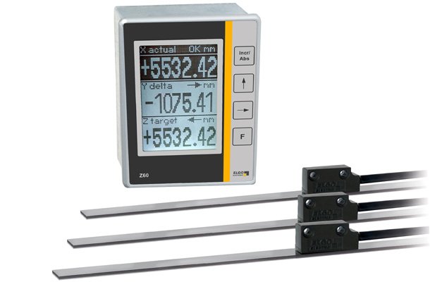
Z60-014 Quasi-absolute Measuring- and Display System for monitored manual adjustments of 1, 2 or 3 axes
The compact position indicator Z60-014 has a graphical LCD display which allows a comfortable and accurate reading of the actual position, target position and the difference (delta) of axes X, Y and Z on manual axis resp. format adjustments. Specific parameters such as offset, tolerance window and measurement unit (mm/inch) can be set individually for each axis. The operating mode of the display can be switched separately for each axis: actual position, target position and delta (difference between actual and target position).
A rechargeable battery cell integrated in the housing of the position indicator transforms the incremental measurement into a quasi-absolute measurement, as the current positions are permanently detected even in the de-energized state and further processed internally.
- Up to 3 axes at a glance during manual axis adjustment: Switchable display of actual position, target position and delta
- Due to the internal accumulator, the actual position is detected permanently (even in de-energized condition)
- Well legible graphical LCD display with units & symbols, e. g. directional arrows and sign for indicated positions
- Specific parameters for each axis separately programmable, e. g. offset, tolerance window and measurement unit
- With serial RS485 interface for PLC communication §
- Power supply 15 ... 30 VDC
Read more about fast and reliable format adjustment
Product inquiryMechanical Data indicator
| Housing | panel housing |
| Housing material | aluminium |
| Housing dimensions (W x H) | 72 x 96 mm |
| Panel cut out (W x H) | 67 x 93 mm |
| Keyboard | foil with short stroke keys |
| Installation depth | 100 mm (with connectors) resp. 37 mm (without connectors) |
electrical Data indicator
| Display | graphical LCD (80 x 120 pixel) |
| Measurement units | mm or Inch |
| Accuracy | ± 1 digit |
| Power supply voltage | 14 ... max. 30 VDC |
| Reverse polarity voltage | integrated |
| Current consumption | max. 600 mA (incl. sensor load) |
| External inputs | 3 control inputs 24 V, PNP |
| External outputs | 3 control outputs 24 V, PNP |
| Interface | RS485 for communication with PLC |
| Connections | 1 x 5-pin and 1 x 9-pin Phoenix connector; 3 x 7-pin M9 round connector (sensors) |
| Power down memory | FRAM for parameters |
| Battery operating time | sensor supply up to 6 or 12 weeks after power-off (depending on selected mode) |
| Battery standby current | approx. 160 µA |
| Optional accessories | NG24.0 (external power supply) |
mechanical daten (Sensor MS2060)
| Housing material | zinc die cast |
| Dimensions (L x W x H) | 30 x 10 x 15 mm |
| Measuring principle | magnetic, quasi-absolute |
| Required magetic tape | MB20-50-10-1-R |
| Magnetic tape pole pitch | 5.0 mm |
| Distance sensor - tape | max. 2.0 mm |
| Max. measuring length | theoretically unlimited |
| Operating speed | normal mode: max. 2.0 m/s enery safe mode: max. 0.5 m/s |
| Connections | 3 screwable 7-pin M9 round connectors |
| Sensor cable | drag-chain suitable, 6-wire, twisted pairs and double-shielded |
| Sensor cable lengthe | 1.5 m (standard), others on request |
| Cable bending radius | min. 60 mm |
| Weight (without cable) | approx. 30 g (cable approx. 60 g/m) |
electrical data (Sensor MS2060)
| Resolution | 0.01 mm |
| Repeat accuracy | ±0.05 mm |
| System accuracy | ±(25 + 20 x L), L=measuring length in ,eter |
environmental conditions entire system
| Storage temperature | -20 ... +70 °C |
| Operating temperature | 0 ... +50 °C |
| Humidity | max. 80 %, non condensing |
| Protection class indicator | front: IP43 (installed) rear: IP20 |
| Protection class sensor | IP67 |
| Influence of external magetic fields on the magnetic sensor | external magnetic fields > 1 mT, whicj directly impinge upon the sensor, can affect the system accuracy |